
After taking a beating for the last four or five years, Killbot wasn’t looking so hot. Getting smooshed into a trailer night after night didn’t help. While on the last tour, we talked about a making a new one. Maestro Sean McGrath took the lead on this one and cobbled together a leaner, more aggressive looking, and tougher version of the costume. When he wants to write a blog detailing how he did that, he’s welcome to. In the meantime, I threw in the LEDs and lit the bitch up, and that’s what I’m gonna talk about here.

The previous Killbot had lighting done to its head. I detailed that in a previous entry last year. When I finally saw the lazer-saw that Sean had built, my mind started whirling with ideas. Originally, he’d planned to have electroluminescent wire wrapped around it. He tried that for one show, but it wouldn’t illuminate very well. I tried working with it, and I’ve decided I hate EL wire. It’s definitely not bright enough for a lit stage and it’s a bitch to work with. I wanted to go another route.
My feeling was that if it was a chainsaw, then it should spin like one. Okay, a real lazer-saw probably wouldn’t spin. But a real robot isn’t made of foam and latex, either. I wanted to make a chaser circuit and wire in a shit ton of LEDs to really make the saw shine.
My best resource through the whole project was a blog on the All About Circuits forum. This guy Bill indexed all his knowledge and a bunch of sample circuits for doing lots of goofy stuff with LEDs. The basic idea for a chaser circuit was to use a 555 timer IC, which sends out timed shots of voltage. This timer would hit a 4017 IC, which sends that voltage down 10 different paths sequentially. Those paths lead to LEDs, which then light up sequentially. Put it in order and they chase each other. And that’s about as simply as I can put it. So I made a breadboard of the circuit.

And it worked. The eight LEDs here lit up sequentially and I could change the speed as well. That’s great for eight little LEDs, but I needed a lot more than that, and bigger. I measured the saw and decided I needed 64 10mm LEDs, as bright as I could get them. I would power these in groups of eight, so the saw actually has eight groups of eight LEDs chasing each other. The mother lode.

All those LEDs will end up hand wired, leg to leg, to fit on the saw. Well, not exactly leg to leg. In order to power those LEDs to their full luminosity and not destroy every single one of them, I had to wire them series-parallel. So now our eight groups of eight are divided further into two groups of four groups of eight. Furthermore, I was likely to blow the 4017 IC chip with that much power consumption going through it, so I had to add a higher power rated 2803 IC that would be signaled by the 4017 IC to pass current directly from the voltage source to each group. Well, I was getting confused, and I think at a thousand words, the diagram I had to draw up explains it all much better.

And from a drawing to reality…

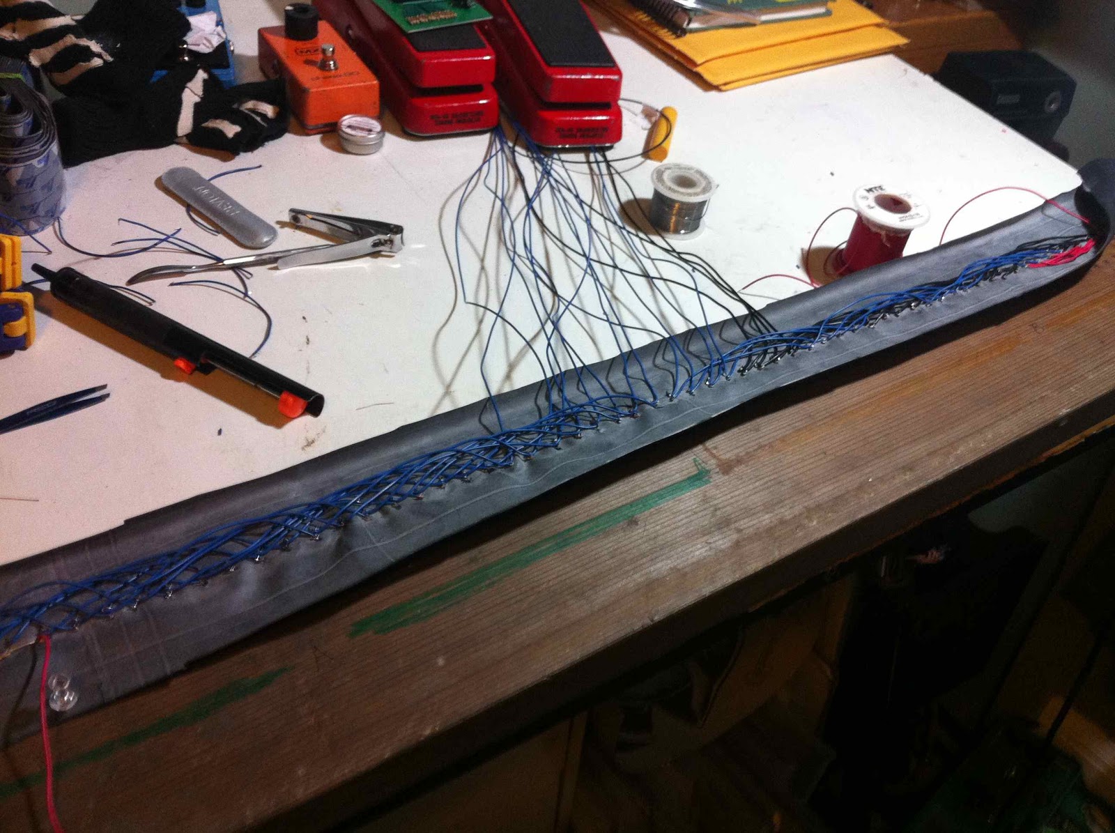
Next I had to wire up the actual LEDs. I needed a way to mount them to the saw that existed, so I poked the LED legs through a cut up bike tire. This worked great, but smelled like shit anytime I got the solder to close to the rubber. It took a long time, many bits of wire, and a bunch of swearing, but eventually I had all the LEDs wired up and ready for the saw.
Fucking spaghetti. I used a Hammond enclosure to house the circuity, because I had one lying around and it fit perfectly into one of the nooks and / or crannies Sean had made into the saw. I attached the LED wires into the circuit.

I glued down the bike tire substrate to the latex and foam saw. It fitted nicely.

I have to admit, I was frightened after all that work that it wasn’t gonna do what I had hoped it would do. And, you know, I had about 15 minutes left until I was supposed to meet everyone at the jam spot. This project deadline was literally down to the wire. But lo and behold, it worked!!
With the lazer-saw finished, there was still the matter of Killbot’s positronic brain. It needed to blink. That’s what positronic brains do, I know, because I saw it on Star Trek: The Next Generation.
Creepy. Mother. Fucker.
Anyway, instead of modding an oversized blinky LED kit from Radio Shack like I did before, I used a circuit from the All About Circuit forum again and used a single 555 IC chip to the job of a couple transistors. I slapped it into an Altoids tin I had lying around.

It fit nicely into a spot I carved out in the brain area.

I also threaded wire through the eye sockets up to the brain. It’s easier to have it all controlled on one switch, methinks, and it’s easily all powered from a single 9V battery.

Voila. This bad ass mother fucker is now ready to go forth and kill.